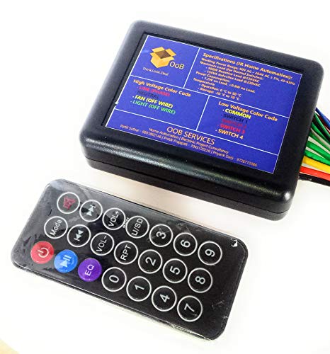


HG Wellness Provides Best Quality products Installation Procedure: Turn off the main Power line. Open the switchboard in which you have to connect the IR module (DTS_IR_410). Now if you want to operate your switchboard only from IR remote, you have to remove all the off wire, line and neutral from board and connect it to IR module (DTS_IR_410). Now if you want to operate your switchboard from both IR remote and physical switches, remove all the wires from the switchboard, connect the off wire to IR module (DTS_IR_410) and at physical switches side, you have to connect all the low volt signal wire with common. After done the wiring, re check it and make sure Phase and Neutral should be in correct position and High volt signal and low volt signal should not mesh up with each other. Now close the switchboard and turn on the main line. If something went wrong, recheck all the connection again or else contact your nearest electrician. If nothing goes wrong, then take the IR remote and press respective button to operate the appliances. Enjoy our IR automation product (DTS_IR_410). IR remote Key Mapping: POWER BUTTON – All On / All Off. 0 BUTTON – Fan Speed Control (Increase the speed of fan from 0 to 5 and then back to 0) 1 BUTTON – LIGHT1 ON / OFF 2 BUTTON – LIGHT2 ON / OFF 3 BUTTON – LIGHT3 ON / OFF 4 BUTTON – LIGHT4 ON / OFF Box Contains: IR Home automation module (DTS_IR_410). TSOP with Switch connector. One sq.mm wire for AC signal. IR Remote. Two Zn-Carbon (Pencil Type) Cell for IR remote. Wiring Diagram (High Voltage Signal): RED – LINE / PHASE. BLACK – NEUTRAL. YELLOW – FAN OFF WIRE. GREEN – LIGHT OFF WIRE (Number 1 to 4 from yellow wire). Wiring Diagram (High Voltage Signal): YELLOW – COMMON (5v GROUND). BLACK – SWITCH1. BROWN – SWITCH2. RED – SWITCH3. ORANGE – SWITCH4.
Trustpilot
4 days ago
3 weeks ago
