Desertcart purchases this item on your behalf and handles shipping, customs, and support to OMAN.
⚡ Control Power Like a Pro — Relay Your Innovation!
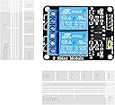
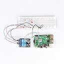
The SunFounder 2 Channel DC 5V Relay Module is a compact, high-performance expansion board designed for seamless integration with popular microcontrollers including Arduino and Raspberry Pi. Featuring two 10A relays with optocoupler isolation and LED indicators, it supports AC250V/DC30V loads and operates on a low 5V trigger current, making it ideal for professional-grade DIY electronics and automation projects.


| ASIN | B00E0NTPP4 |
| Best Sellers Rank | #68 in Single Board Computers (Computers & Accessories) |
| Brand | SunFounder |
| Brand Name | SunFounder |
| Coil Voltage | 5 volts |
| Connector Type | Through Hole |
| Contact Current Rating | 10 A |
| Contact Material | Silver |
| Contact Type | Normally Open |
| Current Rating | 10 A |
| Customer Reviews | 4.6 out of 5 stars 1,298 Reviews |
| EU Spare Part Availability Duration | 1 years |
| Included Components | 2 Channel Relay Module |
| Manufacturer | SunFounder |
| Maximum Switching Current | 10 A |
| Minimum Switching Voltage | 5 volts_of_direct_current |
| Model | 8541582329 |
| Mounting Type | PCB Mount |
| Operation Mode | Automatic |
| Part Number | 2C-5V |
| UPC | 520141421293 |
| Warranty Description | 1 Year Guarantee |
T**N
Works great with micro controllers such as Arduino
Great relays to control larger loads and different voltages. Easy to install using standoff. These relays are easily controlled from devices such as Arduinos that use 5 volt outputs at low currents. Each relays has isolated dry NO and NC contacts.
B**N
Good product
Works well with my arduino to replace a physical switch.
A**B
Works Great!
Recommended!
N**S
Important note about opto-isolation
If you are truly looking to decouple and isolate the device controlling the relay (such as an Arduino, etc) from the relay coils to provide true optoisolation, you must connect it in the following way: Remove the jumper from the JDVCC pin, connect power from a separate 5v power supply to the JDVCC pin and ground from the separate 5v power supply to either of the Gnd pins. Next connect the 5v pin from your controlling device (arduino) to the VCC pin on the 10-pin header of the module, and connect your I/O pins from the Arduino to the 8 control pins. The opto-isolator will get the 5v signal from the Arduino, and the Ground from the Arduino when you perform a digital write LOW on the I/O pin, completing the circuit, and that control circuit is completely isolated from the relay coil power circuit. The gotcha with this board is that the Gnd pin on the 10-pin header and the Gnd pin on the JDVCC/VCC/GND header are actually connected on this board. This means if you connect your Arduino Gnd to either of the Gnd pins on the board, you have now tied your Arduino to the separate 5vdc power supply (which you might not want to do). With all 8 relay coils activated, the board draws 472mA of power - about 50-55mA per relay.
E**A
Relay Energizes on Ground (0V) Signal and general dimensions
4 Stars for: lack of documentation, general OK build quality, and good price. Would Buy Again. Good product for quick deployment to switch a simple load on/off with a PIC micro-controller. Note that a 0V / GND Signal into any input on the relay board will energize / activate the relay, while a 5V signal will de-energize the relay. Relays listed for 30VDC / 125-250VAC both at 10A, but id never trust something with tiny screw terminals to that extent. There is a set of "VCC / GND" Jumpers on the board. I believe this is used to bridge the circuit from the optocoupler output stage to the to use the optocoupler input voltage. You could probably remove this jumper if you want to isolate the power supplies, but I did not test this. Moving the jumper over 1 position just shorts out the board ;). Lastly, attached some general dimensions of the unit if you're building an enclosure or mount for it.
F**O
Good relay board.
Bought this relay board to make a remote control for physically disconnecting a comm bus at a remote site to allow for troubleshooting. It works well being controlled with an arduino.
B**R
Good relay board. CENTER of each relay is common, NC to one side.
This is a good relay board, easy to use and does precisely what I wanted it to do. Wired it to an Arduino that I had assigned relay controls to the relevant pins, was able to correctly control all 4 relays as desired. I misinterpreted the drawings at first and thought that if the three contacts on each relay are A/B/C, that A/B were connected with no power, and A/C were connected when the relay was powered. Well it turns out I'm a dork, A/B are connected with no power and B/C are connected when the relay is powered. Once I figured that out, making everything work was super simple. Small bank of LED indicates when each of the 4 relays is powered, since you can hear the clicking but it's nice to have visual feedback about which relay/s made the noise. Good relay shield.
M**O
Exactly what I needed
This module is perfect! It comes all soldered and has the screw-in terminals. Like almost all relays of this type it can't handle more than 10 A. In the rest of the world that would be no problem since 230 V breakers trip at 10 A. But in North America, with 15 A and 20 A circuits, this is not going to work. That limits you to devices 1200 W or less. My first project with it is a system to water plants. The pump only requires 4-12 V and probably a few hundred milliamps. By the way, if you want to power bulbs or for many other applications, I recommended using DC voltage. The bulbs will light up just the same, but it will be much less dangerous than dealing with AC. ONE PROBLEM: It lacks labeling of the relay terminals. NO Normally Open, C Common, NC Normally Closed are not printed. ONE GIANT ADVANTAGE: This module compared to others is great because you supply 5V to it through a separate pin, so you don't have to provide the required current on the input pin. The module does that for you. Many boards out there will have only an input pin, which you can't use directly, you'll have to build the missing circuitry so you can control the relay with your Arduino or whatnot. Plus some boards are missing the very important diodes! It also has one status LED per relay so you know what's going on at all times. Note that it is active low.
D**G
It works directly off a Raspberry PI
I spent a couple of weekends trying to get one working for the Arduino with no success, This came plugged into to Pi and heyy presto. No fiddling around nothing, works like a dream too.
E**N
De calidad, barato y seguro
Este Shield es de muy buena calidad y además facilísmo de utilizar: Conectas Vcc y GND y luego las salidad de tu arduino(u otro microcontrolador) a las cuatro entradas disponibles. Cabe destacar como otros muchos usuarios, que la lógica es invertida; es decir, cuando la salida del arduino es HIGH, el relé esta apagado y viceversa.
N**S
Good dual realays for a Rasberry Pi
These have worked perfectly with a rasberry pi to make a garage door controller
T**T
Perfect for isolated control of electronics
I am using these relays to control LED strip lighting. The controller operates on 5VDC and the lights require 12VDC. These relays provide a perfect solution. The optocouplers provide an added level of isolation. The relay coils operate on low current 5VDC. The output contacts can handle high current loads of different voltages. There is a set of NO and NC contacts for each relay. Each relay is operated independently. I recommend this product for anyone that requires isolation between the controlling circuit and the output load.
E**D
Five Stars
Great relay board, bargain for the money. Only time will see how long it lasts
Trustpilot
4 days ago
3 weeks ago